555 Timer Schematic / 555 Timer Circuit Schematic | Electronics projects, Timer ... : 555 timer was first introduced by signetics corporation in 1971 as se555/ne555.
byAdmin-
0
555 Timer Schematic / 555 Timer Circuit Schematic | Electronics projects, Timer ... : 555 timer was first introduced by signetics corporation in 1971 as se555/ne555.. The 555 timer ic is a very cheap, popular and useful precision timing device which can act as either a the difference this time is that the two transistors have been replaced by the 555 timer device. You may already know that se/ne 555 is a. This article covers every basic aspect of 555 timer ic. In the schematic above, notice that the. With this information you will learn how how the 555 works and will have the experience to build some.
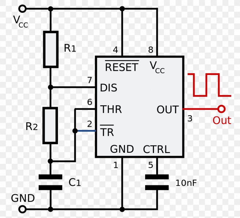
Connect power and ground to pins 8 and 1 of the 555. Learn about the 555 timer and how it works in astable mode. The ic can operate in three different modes such as astable. With this information you will learn how how the 555 works and will have the experience to build some. Derivatives provide two (556) or four (558) timing circuits in one package.
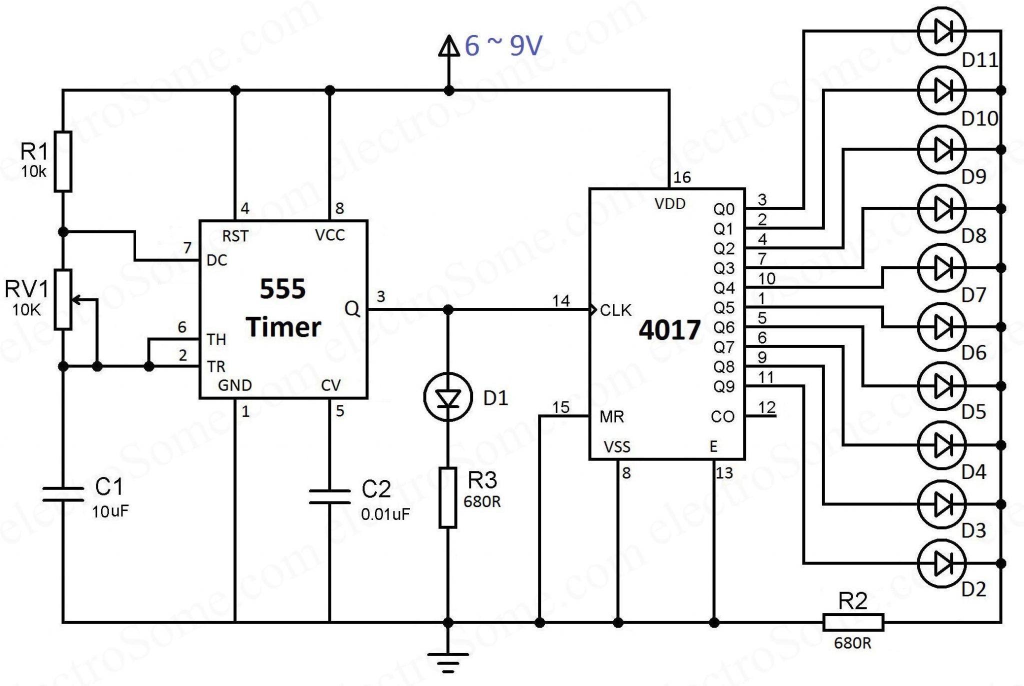
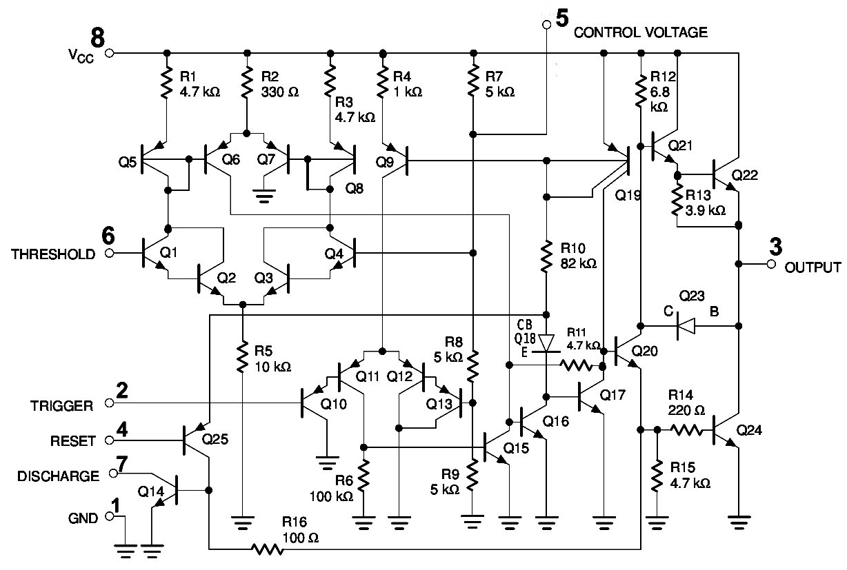
LED Chaser sử dụng 4017 Counter và 555 Timer from electrosome.com The 555 timer ic is an integrated circuit (chip) used in a variety of timer, pulse generation, and oscillator applications. The schematic shows (3) circuits, because one circuit does not work well over the entire vcc range. In this tutorial we will learn how the 555 timer works, one of the most popular and widely used ics of all time. The xx555 timer is a popular and easy to use for general purpose timing applications from 10 µs to hours or from < 1mhz to 100 khz. They are a universal standardized way to give a graphical representation. This article covers every basic aspect of 555 timer ic. • introduce the 555 timer. The ne555, sa555, and se555 monolithic timing circuits are highly stable controllers capable of producing accurate time delays or.
In the schematic above, notice that the.
In the schematic above, notice that the. The 555 can act as either a simple timer to generate single pulses for time delays, or as a relaxation. It is a affordable, stable and user friendly ic in application such as monostable and bi stable. • introduce the 555 timer. The ic can operate in three different modes such as astable. You may already know that se/ne 555 is a. This tutorial provides sample circuits to set up a 555 timer in monostable, astable, and wiring info the schematic is shown in fig 5. Slfs022e − september 1973 − revised march. It's a simple source of oscillating in astable mode, the output cycles on and off continuously. Connect power and ground to pins 8 and 1 of the 555. The 555 timer ic is an integrated circuit (chip) used in a variety of timer, pulse generation, and oscillator applications. The schematic shows (3) circuits, because one circuit does not work well over the entire vcc range. Derivatives provide two (556) or four (558) timing circuits in one package.
Connect power and ground to pins 8 and 1 of the 555. The standard 555 timer ic is used in a variety of timer, pulse generation and oscillator applications. 555 timer was first introduced by signetics corporation in 1971 as se555/ne555. This article covers every basic aspect of 555 timer ic. In the schematic above, notice that the.
555 Timer IC Electronic Circuit Astable Multivibrator ... from img.favpng.com You can watch the following video or read the written tutorial below. With this information you will learn how how the 555 works and will have the experience to build some. D timing from microseconds to hours d astable or monostable operation d adjustable duty cycle. The first simply uses a normal 2n3904 garden variety transistor, and. In the schematic above, notice that the. The 555 timer is a simple integrated circuit that can be used to make many different electronic circuits. The schematic shows (3) circuits, because one circuit does not work well over the entire vcc range. Learn about the 555 timer and how it works in astable mode.
The schematic shows (3) circuits, because one circuit does not work well over the entire vcc range.
It's a simple source of oscillating in astable mode, the output cycles on and off continuously. The schematic shows (3) circuits, because one circuit does not work well over the entire vcc range. D timing from microseconds to hours d astable or monostable operation d adjustable duty cycle. The ne555, sa555, and se555 monolithic timing circuits are highly stable controllers capable of producing accurate time delays or. Connect power and ground to pins 8 and 1 of the 555. Slfs022e − september 1973 − revised march. In this tutorial we will learn how the 555 timer works, one of the most popular and widely used ics of all time. The xx555 timer is a popular and easy to use for general purpose timing applications from 10 µs to hours or from < 1mhz to 100 khz. The 555 timer ic is an integrated circuit (chip) used in a variety of timer, pulse generation, and oscillator applications. They are a universal standardized way to give a graphical representation. Learn about the 555 timer and how it works in astable mode. 555 timer was first introduced by signetics corporation in 1971 as se555/ne555. With this information you will learn how how the 555 works and will have the experience to build some.
• introduce the 555 timer. The first simply uses a normal 2n3904 garden variety transistor, and. Learn about the 555 timer and how it works in astable mode. It is a affordable, stable and user friendly ic in application such as monostable and bi stable. This article covers every basic aspect of 555 timer ic.
555 Timer IC Pin Diagram Features And Applications | 555 ... from circuitspedia.com With this information you will learn how how the 555 works and will have the experience to build some. The 555 timer is a simple integrated circuit that can be used to make many different electronic circuits. Connect power and ground to pins 8 and 1 of the 555. 555 timer was first introduced by signetics corporation in 1971 as se555/ne555. • introduce the 555 timer. The schematic shows (3) circuits, because one circuit does not work well over the entire vcc range. The 555 timer ic is a very cheap, popular and useful precision timing device which can act as either a the difference this time is that the two transistors have been replaced by the 555 timer device. It's a simple source of oscillating in astable mode, the output cycles on and off continuously.
The 555 can act as either a simple timer to generate single pulses for time delays, or as a relaxation.
The ne555, sa555, and se555 monolithic timing circuits are highly stable controllers capable of producing accurate time delays or. • introduce the 555 timer. The ic can operate in three different modes such as astable. D timing from microseconds to hours d astable or monostable operation d adjustable duty cycle. You can watch the following video or read the written tutorial below. It's a simple source of oscillating in astable mode, the output cycles on and off continuously. The 555 timer is a simple integrated circuit that can be used to make many different electronic circuits. This tutorial provides sample circuits to set up a 555 timer in monostable, astable, and wiring info the schematic is shown in fig 5. It is a affordable, stable and user friendly ic in application such as monostable and bi stable. With this information you will learn how how the 555 works and will have the experience to build some. In the schematic above, notice that the. Learn about the 555 timer and how it works in astable mode. The xx555 timer is a popular and easy to use for general purpose timing applications from 10 µs to hours or from < 1mhz to 100 khz.